Sensor fusion with Raspberry pi camera, Radar and ROS for Turtlebot3
Sensor fusion has always been a topic that fascinates me for two simple reasons: first it’s widely used in autonomous systems like self-driving cars and robot vacuums and second, given its complexity, it can be a great learning experience. There are solutions already available but they either require very expensive hardware or a great deal of expertise making them unreachable for engineers that just want to have some serious fun and learn a lot with robots. With that in mind, I decided I would like to develop a ROS package that takes data from a radar and a camera and does sensor fusion to boost turtlebot3’s capabilities. In the following sections I will go over the different steps necessary to achieve that goal.
Robot set up
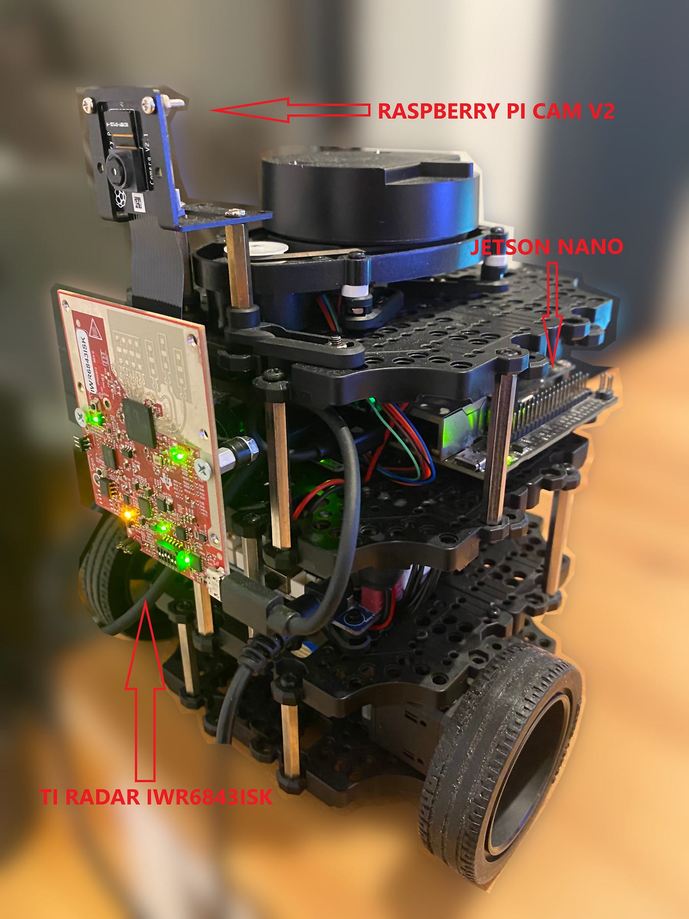
I will be using some incredible tools that any roboticist might be familiar with, ROS (Robot Operating System), Turtlebot3 burger, jetson nano, raspberry pi camera v2 and Texas Instruments (TI) radar IWR6843ISK. I will not go over details over each component since there is a lot information out there and I will be sharing useful links later in the article.
Turtlebot3 is already equipped with a 1-channel 360 Lidar but lacks a visual system that lets you control the robot remotely and safely. Furthermore, the Lidar is mounted around 17 cm above its base so any obstacles below it will not be seen, leaving the precious robot exposed to danger. The camera is mounted on top of the radar so they have the same plane. Here is what the final version of the robot looks like:
Sensor fusion
After the boosted version of turtlebot3 is ready and visible for ROS I can proceed to what I believe is the most interesting part of the project, fusing the data from the radar and the camera.
Radar and Camera Data
Texas Instruments has developed and shared a ROS package that handles all configurations and publishes all the data generated by the radar as a point cloud message of type sensor_msgs/PointCloud2. Furthermore, they also share a similar example with a rather old version of the turtlebot doing autonomous navigation that serves as an example to easily integrate to turtlebot3.
For the raspberry pi cam, the integration with ROS and the robot took less time thanks to the jetson_camera package. The package publishes a message of type sensor_msgs/CompressedImage which can be used to access the image pixels.
Message synchronization
In order to fuse the data from two different messages a synchronization mechanism is necessary. This can be achieved by using a ROS synchronization policy, namely message_filters::sync_policies::ApproximateTime. This is a very useful way to register a callback function that takes as parameters two different types of messages. In this particular case the function is defined as:
Inside this function there are three main steps that need to be done in order to fuse the data from the two sensors. First, we need to obtain the actual data from the two messages, that is, the pixel values of the image and the point cloud. Second, we need to transform the point cloud from the radar’s frame to the camera’s frame. Finally, it’s necessary to project each cloud point into the image plane of the camera. The following code carries out all three steps:
Nice! We can now have some sense of depth with a raspberry pi camera and a radar doing actual sensor fusion!
ROS visualizations and proof of fusion
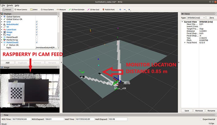
To test the fusion code I set up a monitor in front of the robot at an 85cm distance. When the robot is not moving, the point cloud coming from the radar is not constant, unlike other depth or stereo sensors. However, I was getting continuous points from the surface of the monitor even when it was not moving. Here is an Rviz visualization of the testing environment:
To check if the fusion was actually working, I further modified the fusion callback function to also publish another image with all the points that have been successfully projected onto the image plane and the distance at which they are located from the robot. The final version of the callback function that draws points on the image and the estimated distance from the robot is:
Now we only need to subscribe to the fused topic that is being published and check if those points are accurate:
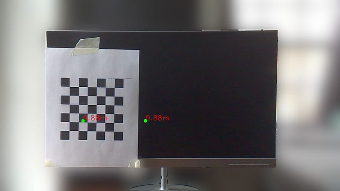
Cool! It’s telling us that the monitor is 88 cm far from the robot (real distance is 85 cm). This is a very descent estimate for a simple home fusion set up!
Final remarks
Before I conclude I would like to go over some of the challenges I encountered:
- The original ROS driver shared by TI is not publishing the ROS time, so the synchronization policy was not working! It took me some time to figure that out.
- I modified the original turtlebot3 ROS packages to be able to integrate the radar and the camera.
- I did not go over the camera calibration process but it’s necessary in order to project the cloud points into the image plane.
The radar package is also publishing another custom message with more interesting data like angular velocity of the points which is a very appealing solution for path planning. For now I wanted to keep it simple and just read the XYZ coordinates of each point but I do intend to extend this package so keep an eye out for future articles!
References
[1]: Rahul Kumar and Sujay Jayashankar (2019). Radar and Camera Sensor Fusion with ROS for Autonomous Driving
[2]: Ziguo Zhong and Aish Dubey (2018). Camera Radar Fusion for Increased Reliability in ADAS Applications
[3]:Ankit Dhall et al. (May 27 2017). LiDAR-Camera Calibration using 3D-3D Point correspondences
[4]: Autoware LiDAR-Camera Fusion. https://gitlab.com/autowarefoundation/autoware.ai/autoware
[5]: AinsteinAI ainstein_radar. https://github.com/AinsteinAI/ainstein_radar